Mine trailing cable repair—verified under movement.

Arkon restores trailing cable as a complete electrical and mechanical system, evaluates pilot-circuit stability through dynamic reeling, and documents the basis for repair, further evaluation, or retirement.

01Dynamic pilot verification
02Advanced fault location
03Insulation diagnostics
Technical scope

Static continuity is the starting point—not the finish line.

A cable can appear electrically continuous while stationary and still reveal an intermittent pilot problem as it bends, reels, or changes lay. Arkon evaluates the repair as a whole system: conductor path, insulation, shielding, grounding, pilot integrity, jacket restoration, and the evidence needed for a responsible disposition.

How Arkon can support you
  • Cable condition assessment and repair planning
  • Conductor, ground, pilot, and shield repair or splicing
  • FBS exothermic conductor joints where the repair specification permits
  • Insulation rebuilding, stress-control, and jacket restoration
  • TDR prelocation and thumper fault pinpointing
  • VLF withstand, tan delta, partial-discharge, and dynamic pilot verification
  • Repair identification, results documentation, and backlog coordination
How Arkon evaluates a repair

Evidence built around real cable duty.

Repair quality should be demonstrated in conditions that reflect how a trailing cable works. Arkon combines dynamic pilot verification with fault-location and insulation diagnostics so the result explains more than whether the cable simply conducts while stationary.

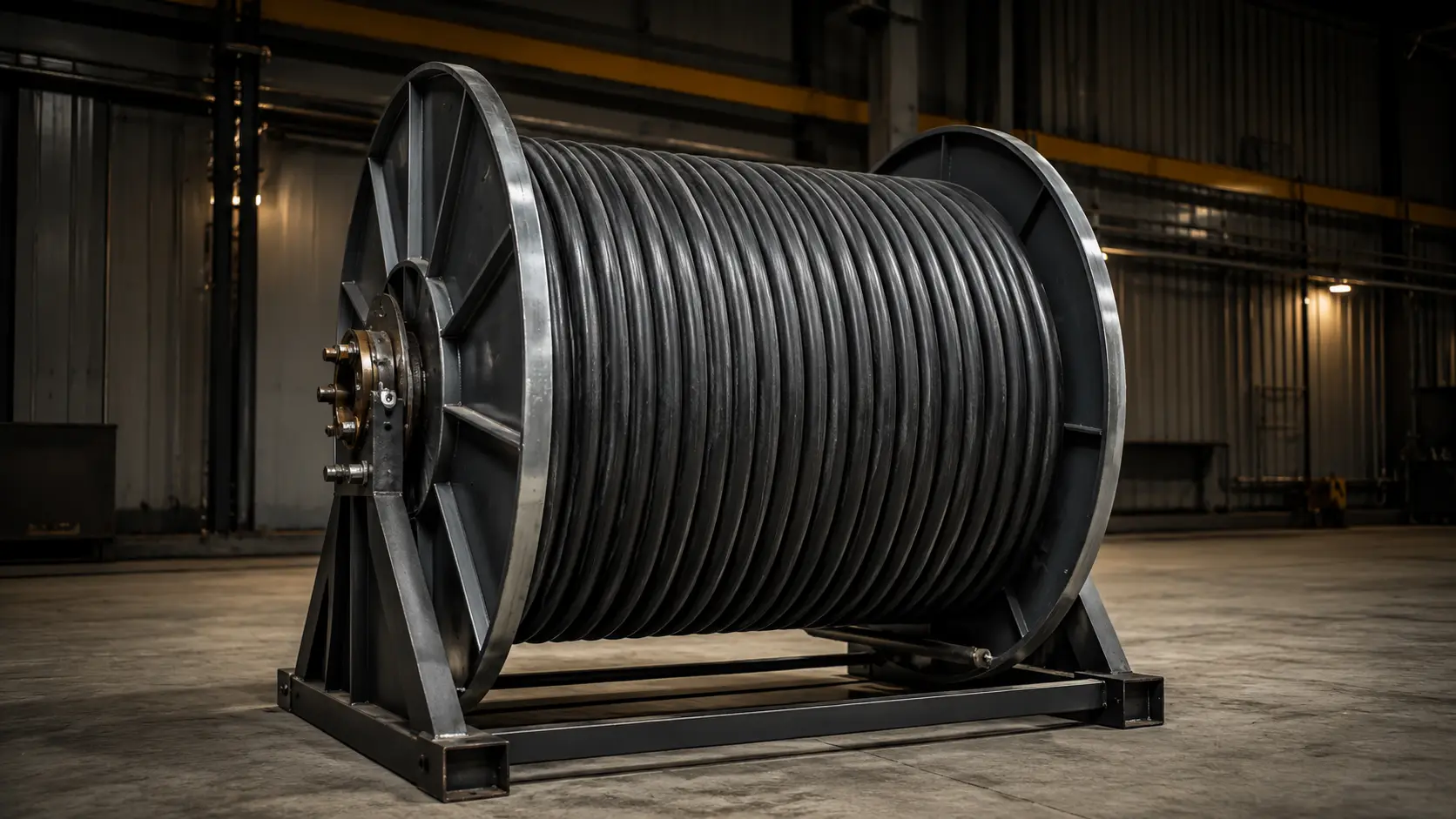
Heavy-duty black trailing cable wound on a steel reel in a maintenance facility
Dynamic pilot verification

Proving continuity under movement.

A stationary check can miss an intermittent pilot condition that appears only as the cable bends, changes lay, or moves through a reel. Arkon evaluates pilot-circuit resistance through representative reeling movement and watches for change across the dynamic cycle.

≤ 1.0 ΩMaximum allowable pilot-circuit resistance change through the dynamic cycle

Arkon acceptance criterion: any change greater than 1.0 Ω is rejected for correction, further evaluation, or a retirement recommendation.
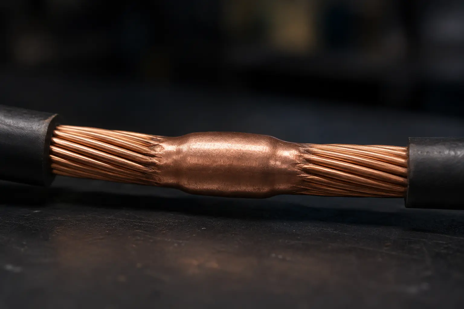
Close-up of an exothermically formed copper joint between stranded conductors
FBS exothermic joints

A metallurgical conductor connection.

FBS means Flexible Butt-End Splice. Where cable construction and the approved repair specification permit, prepared conductor ends are joined in a butt-end geometry through an exothermic process that forms a metallurgical copper connection.

The resulting current path does not depend only on sustained mechanical compression. Its compact geometry also supports a disciplined rebuild of the surrounding cable layers, with the final joint selected and restored for the specific cable.

Quality gates

From diagnosis to documented disposition.

Each gate protects the next. A cable is not cleared simply because one reading looks acceptable; the repair must make sense electrically, mechanically, and operationally as a complete system.

  1. 01

    Identify & assess

    Confirm cable identity, construction, damage extent, and repair suitability.

  2. 02

    Locate & diagnose

    Apply the appropriate fault-location and insulation-condition diagnostics.

  3. 03

    Rebuild conductors

    Restore conductor, ground, pilot, and shield systems as the repair requires.

  4. 04

    Restore cable layers

    Rebuild insulation, stress-control, shielding, and the protective jacket.

  5. 05

    Challenge & verify

    Confirm withstand integrity and evaluate pilot stability through reeling movement.

  6. 06

    Document disposition

    Record acceptance, corrective action, further evaluation, or retirement.

Electrical test insight

Five tests. Five different answers.

No single test answers every cable question. Fault-location tools show where a defect is, withstand testing shows whether repaired insulation can hold, and condition diagnostics explain how the insulation is behaving. Arkon selects the combination that fits the cable, fault, and repair.

01Fault pinpointing

Thumper

What it reveals. A controlled surge makes a fault respond at its physical location, creating an acoustic and electromagnetic signature that can be followed to the damaged point.

Why it matters. It turns an estimated distance into a practical repair location, reducing unnecessary cutting, stripping, and time spent opening sound cable.

02Distance & cable map

TDR

What it reveals. Time-domain reflectometry shows reflections from opens, shorts, and impedance changes, then estimates their distance from the test end.

Why it matters. It quickly narrows the search area, identifies cable landmarks, and provides a trace that can be compared before and after repair.

03Insulation withstand

VLF

What it reveals. Very-low-frequency testing applies controlled AC stress to determine whether repaired insulation can sustain a defined test level without breakdown.

Why it matters. It provides a direct return-to-service integrity check and can expose a severe weakness before the cable is placed back under operating duty.

04Whole-cable condition

Tan delta

What it reveals. Dielectric-loss measurement provides an overall view of insulation behavior, including indications consistent with aging, moisture ingress, contamination, or nonuniformity.

Why it matters. It can identify a cable that passes a withstand test yet shows elevated or changing losses, improving repair, monitor, or retirement decisions.

05Localized insulation activity

Partial discharge

What it reveals. PD diagnostics detect localized electrical activity associated with defects in insulation, splices, terminations, or interfaces and can help estimate where that activity originates.

Why it matters. It helps distinguish an active weak spot from broader insulation aging, allowing repair effort and follow-up decisions to focus on the actual condition.

The combined value

TDR and thumper techniques shorten the path to the fault. VLF establishes a withstand result. Tan delta and partial discharge add whole-cable and localized condition insight. Together, they support a more informed repair, return-to-service, monitoring, or retirement decision.

Related field guide

Plan the complete return-to-service record.

Our field guide explains how identification, damage assessment, layer-by-layer restoration, verification, and documentation support a defensible cable disposition.

Read the trailing cable repair planning guide

Bring the cable condition, history, and operating need.

Review a cable repair need